Test hall
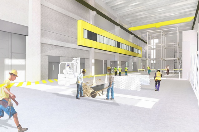
A 3D concept image of the test hall.
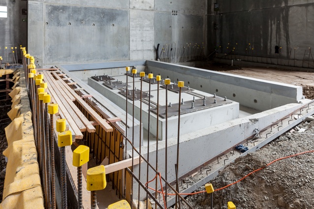
The shake table, which is used for applying forces to an object that simulate an earthquake.
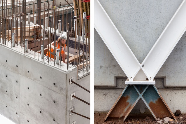
Formwork is set up for one of the strong walls and the structural steel bracing is exposed on the front elevation.
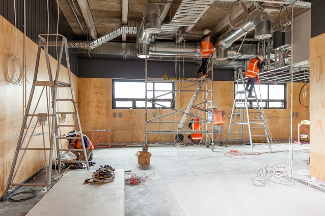
Works proceeding in the materials test lab.
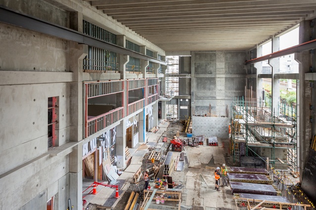
An aerial view of the testing hall, with the strong floor and walls, and gantry crane rails overhead.
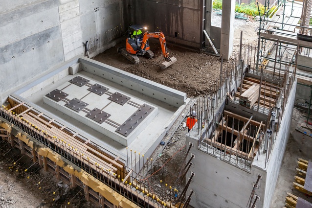
The shake table and one of the string walls under construction.
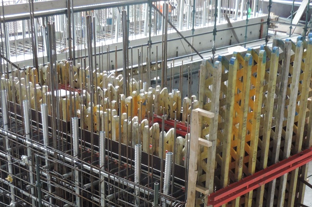
Peri Formwork is utilised to construct the strong walls - fixing sleeves, post tensioning ducts and reinforcing still exposed.
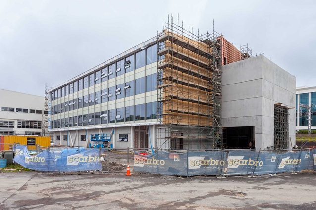
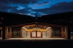
Exterior view from Khyber Pass.
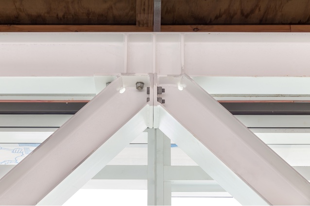
Exposed internal structural steel bracing.
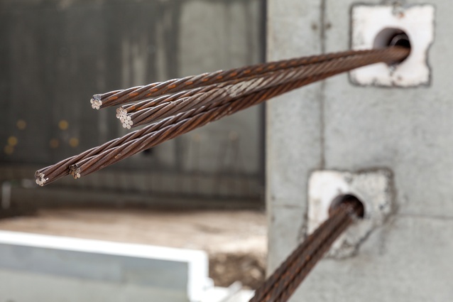
Tendons protruding from a strong wall pending design MPa for post tensioning.
While it doesn’t look like anything out of the ordinary from the exterior, this four-storeyed concrete and steel facility houses the largest seismic testing facility in Australasia.
When complete, this building on the former Lion Breweries site will form part of the Unviersity of Auckland’s (UoA) Newmarket Campus where four renovated brewery buildings, along with this new facility will make up a hub for post-graduate enineering research.
Scarbro Construction, who won the tender to construct the UoA Faculty of Engineering Structures Hall (Building 906) in December 2013, took on the project with extensive knowledge behind them, thanks primarily to directors Garry Scarborough and Peter de Nys who conducted in-depth research about building sesimic testing facilties. Post tender, project manager Michael Cairns worked with Australian firm Kane Construction, who built a similar facility at Melbourne’s Swinburne University in 2011. “This allowed us to discuss and compare building methodologies, which imparted further confidence that our approach was comparable,” Cairns said.
The facility is essentially, and was built as, two separate buildings, converging only on the top floor, level four, to become a unified structure. For Cairns, this enabled ease of management
as two separate teams worked concurrently on what was treated as two projects for the majority of the build.
When Progressive Building visited the site in late October 2014, the build was well on the way to completion (scheduled for February 2015). The ground floor is comprised mainly of the testing hall, an impressive area measuring 14 metres from the ground level to the underside of Level 4.
“This building will have the largest seismic testing capabilities in Australasia. With structural testing walls reaching nine metres, it has the capacity for buildings up to three storeys to be earthquake assessed. Steel sleeves cast within these concrete strong walls and floor allow for fixings to hold the test structures in position,” Cairns said.
“Our brief was to produce a strong wall structure (consisting of a two-cell, four-cell and 1000mm-thick wall) and 600mm thick strong floor with 1,273 cast-in steel sleeves at 500 centres in each direction, flush with the finished F5 concrete surface.”
The strong floor spans 255 m² and includes 722 inserts or sleeves. It weighs in excess of 420 tonnes. Cairns said it required a pour of 153m3 of concrete. “It was pumped at a rate of 50m3 per hour, taking three hours from start to finish. The floor incorporates 722 50mm sleeves cast the full depth of the floor at 500 centres each way. Thirteen tonnes of reinforcing went into the strong floor, which was post tensioned in two directions.”
The lower, basement slab is 400mm thick and used 112m3 of concrete. It required 9.77 tonnes of reinforcing also post tensioned both ways.
The 1000mm thick wall stands five metres tall and incorporates 171 steel sleeves. But it was the strong wall cells and floor that required the most due diligence in this project. The core of each cell of the strong walls and floor is accessible via a small enclave through which researchers will be able to crawl into and adjust or attach bolts. A portion of the strong wall works in conjunction with the testing hall’s shake table, another unique and challenging structure to build.
The shake table is capable of imposing a 250kn horizontal force on a test structure and can simulate earthquake conditions of up to +/- 200mm horizontal displacement at up to 0.6m/s. This took some precise planning to construct; the university’s engineer took part in the process, which included a three-stage pour in order to maintain the precise placements of its components.
Two gantry cranes will operate on rails in the testing hall, each with a lifting capacity of 10 tonnes. Together, they will be able to cover 50 metres from end to end and locate the given test structure accordingly.
Due to the requirement for the sleeves to be precisely placed, Cairns said four sample pours were completed for each strong wall, and the floor. “Although this was intially to achieve sign-off from the client, it also identified any issues. From this process, we learnt that you can be presented with either a concave or convex meniscus between the sleeves. This occurs when a liquid, in this case the concrete, meets a solid object, the sleeve.
“Our first wall pours had some of the sleeve ends sitting slightly (1mm) proud of the concrete face. This happened as the inside face of the form ply, attached to the Peri formwork, tightened up unevenly (racked) on the ends of the steel sleeves that were digging into the ply.”
This issue was resolved by seeking the advice of an automotive mechanic and requesting the principles that are applied to torqueing the head of a car engine were applied to the formwork. “A tightening pattern or sequence for the wall ties (divvy dags) was developed, including the crucial torque settings being applied with the use of a torque wrench.”
To elimate the translation of vibrations throughout the building during testing, a 20mm vibration separation was required along the perimeter of the strong floor and shake table.
The other side of the building mainly consists of office and teaching spaces. On the ground floor, a timber conditioning room, a fog room, and timber workshop areas sit ajacent to the testing hall.
On Level 4, the two buildings join as one, with offices on one side (Level 4a), and above the testing hall (Level 4b), a significant clear space, which at this stage will be left vacant for future development.
The building itself is predominantly a concrete structure made up of precast shear walls and floor units, although a significant amount of in-situ concrete works were associated with the testing hall and strong walls and floor contained within it.
The building is wrapped in a combination of unitised curtain wall glazing, precast panels and accoya timber vertical shiplap cladding, which make up the building envelope. The exterior also features a diagrid of white painted structural steel, which while striking, gives little of the building’s complex interior workings away.